
Page 6 - Astro-Catalog2020.11
P. 6
VISUAL INSPECTION The TIR allowed includes a maximum of .005 TIR assignable to the
each contact is inspected under a microscope to make certain the contact during its manufacture. (TIR is an abbreviation for Total
indenture does not crack or tear the base metal, or cause excessive Indicator Reading and is a measure of the total deviation from a true
distortion of the contact. center line when the item being measured is rotated through 360 °.)
CONTROLLING CRIMP DEPTH COMPRESSION FORCES
From the tensile curves, a known crimp depth range is established. Crimping compression forces are directly related to: A. Indenter GeNeRAL CRIMPING INFORMATION
It is imperative, therefore, that the crimp tool settings be within the Configuration; B. The Amount of Leverage in a Crimping Tool; C. Crimp
established tolerance. Depth Required for Satisfactory Results; D. Contact Hardness and
Contact-Conductor Combinations.
To insure full closure of the tool handles and positive bottoming, it is
necessary that tools be cycle controlled. This is accomplished by the use A. Indenter Configuration
of a precision ratchet device which releases the handles at the positive MS drawings are specific as to indenter configuration of the Class I
bottoming position within specification tolerances. This release point crimping tool. It is possible to change the shape of the indenters to
and positive bottoming are applicable to all contact sizes. reduce frontal area and thus reduce crimping forces. If the reduction
of compression forces was the only factor involved, a knife blade
MEASURING CRIMP DEPTH (GAGING) edge on an indenter, or a conical tip shape would be the most
Too loose a crimp setting will result in wire pullout and high millivolt desirable configuration. But this would result in cracked contacts,
drop (high resistance). Too tight a setting will nick the wire strands damage to plating, high wire embrittlement because of the
causing low tensiles and wire breakage within the contact. concentrated stress of a small crimp area, and would also result
Positive bottoming tools can readily be gaged by selecting gage pins in marginal tensile values.
dimensioned to the end limits of the known crimp range of a given B. The Amount of Leverage in a Crimping Tool
contact. Leverage or linkage systems could be devised to minimize the amount
AXIAL DEFORMATION of crimp compression forces. Archimedes’ old adage could apply here
During the crimping process considerable force is applied and material wherein he says, “Give me a place to stand and to rest my lever on
displacement takes place, which may result in axial deformation of the and I can move the earth.” From a practical viewpoint, however, the
contact. The following factors contribute to axial deformation of contacts: geometry of Class I tools under MIL-T-22520 are specific in tool length
and width.
1. Contact material and contact hardness.
2. Crimp barrel wall thickness. C. Crimp Depth Required for Satisfactory Results
3. Concentricity of conductor hole to O.D. of crimp barrel. Another way to reduce compression forces is to vary crimp depth.
4. If an insulation support is included on the contact, the concentricity MS drawings are specific in designating crimp depths. It is
of this support (I.D. and O.D.) with respect to the other diameters in understandable that the less the indenters indent the lower the
the contact. compression forces involved. On the other hand, if the tool does not
5. Crimp depth - the deeper the crimp the greater the possibility of indent as deeply as specified, the possibility exists that sub-marginal
contact bending. or marginal tensile values will result.
6. Conductor characteristics - conductor hardness, number of strands, D. Contact Hardness and Contact-Conductor Combinations
size of wire, bunching of strands, the lay of the conductors, plating Contact material is definitely a factor contributing to high
or the use of solid conductor. compression forces. Some contacts are made of hard material; some
7. The condition of the indenters - indenters which are not uniformly contacts have thick walls and some contacts are required to cover a
dimensioned or aligned or which have extreme variation in surface range of conductors, all of which could involve high crimping forces.
condition can cause contact bending. It is felt that an analysis of these conditions and an attempt to make
8. The condition of the crimping tool - a worn crimping tool can them compatible with the crimping tool could facilitate the reduction
contribute to contact bending. of compression forces.
9. Method of contact location and support - improperly supporting or
positioning the contact in the tool can result in contact bending. As can be seen from this brief review of crimping, many factors
10. Method of measuring axial deformation - we have found that influence the effectiveness of a crimped joint. However, a good crimping
this is one of the least understood items relating to the crimp tool compensates for many of these factors by providing proper crimp
tool specification. depths, resulting in termination having high tensile strength, low
millivolt drop, and minimum contact deformation. With the use of
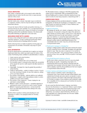
MIL-DTL-22520 is specific in defining and evaluating the axial a well-engineered tool, crimping becomes one of the most reliable
deformation of contacts. This paragraph allows the following methods of wire termination.
deformation:
fIG. 3 Contact size Contact Deformation
A glossary of connector terms is available at www.astrotool.com.
20 & smaller .011 TIR
16 .012 TIR
12 .012 TIR
5
© Copyright 2008 Astro Tool Corp. , 21615 SW Tualatin Valley Highway, Beaverton, OR 97006 • Tel: (503) 642-9853 • www.astrotool.com