
Page 5 - Astro-Catalog2020.11
P. 5
Crimping Pin and socket Contacts
CRIMPING CRIMP DEPTH DETERMINATION
Crimping may be defined as the art of joining a conductor to a pin or Having resolved an indenter design, the determination of crimp depth
socket contact by controlled compression and displacement of metal. range must be established for each application. There are many factors
It has been used for many years. which contribute to the selection of the proper indenter setting. These are
primarily related to contact material and dimensions as well as wire type
In a good crimp joint, there is a mutual metal flow causing symmetrical and size.
distortion of wire strands and contact material. The mil cross-sectional
area is but slightly reduced and all voids are practically eliminated. The proper crimp depth for a given contact is the one that yields the best
Such a joint is similar to a cold weld. Mechanical strength and good mechanical and electrical joint. To determine this setting, many contacts
electrical continuity are established. Because of the new environments of the same type are crimped though a range of indenter settings from
to which electrical connectors are subjected, there has been a drastic too loose to too tight. The crimped contacts are then subjected to tensile
change in thinking relative to the use of precision crimp joints in and voltage drop tests.
preference to solder.
WIRE PREPARATION
CRIMPING CONFIGURATIONS Proper wire preparation also plays an important part in making a
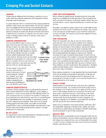
There are many different types of crimps employed fIG 1 good crimp joint. There are two popular methods of wire stripping —
today. These range from the terminal fold-over mechanical and thermal. During the mechanical stripping process,
tab type of crimp to the single indent crimp, the extreme care must be taken to avoid nicking or removing wire strands,
dual indenter crimp, the three indenter crimp, hex otherwise a loss of tensile strength will result. Conversely, if the
crimps, and, finally, the MIL standard four indenter insulation is not completely removed, erratic values may be obtained.
crimp. The four indenter crimp (Fig. 1) provides Heat stripping eliminates the danger of nicking strands. However,
the most uniform displacement of wire and depending on the type of insulation being stripped, too much heat can
contact material. The wire strands and the contact 4-Indenter Crimp cause actual charring of the insulation or decompose the insulation with
material are formed together in a solid mass with Cross-section the evolution of corrosive gases which react with the conductor platings.
little or no reduction of the mil area of the wire across axis There is also a possibility of local annealing of the conductor. Too little
strands. A minimum of voids exists and very little heat can deposit an insulation film which can act as a lubricant. Any of
extrusion of the wire strands takes place. these conditions can affect tensile results. Wire preparation is, therefore,
another area that requires control if proper tensiles are to be achieved
The four indenter crimp principle with a wire-contact combination.
has been used to produce a fIG 2
variety of impressions, the most Before making a tensile test it is also important that the stripped length
common being the “bathtub” of the wire be checked to ensure that the wire extends all the way into
and “octadent” (also called the contact wire barrel. During the tensile test it is necessary for the
double indent) (Fig. 2) The octadent Crimp – uncrimped end of the wire to be held in such a way that the pull force is
octadent configuration has Horizontal Cross-section evenly distributed to all the strands.
been chosen by the Military for
use in the M22520/1 and /2 tools. TENSILE TESTING
Tensile testing is a controlled pull test on the crimp joint to determine
CRIMPING CHARACTERISTICS its mechanical strength. It is a destructive test which usually results in
Connectors utilizing crimping contacts usually permit the removal of wire breakage in the crimped barrel, the wire pulling out of the crimped
these contacts several times so that modification, circuit changes, or barrel, or wire breakage outside of the crimped area. The method and
replacement of contacts may be made with little difficulty and with the device used to conduct this test have a direct bearing on the results
same quality assurance as in production line assembly. Crimping may obtained. Per specification, the testing device pulls at the rate of one
be accomplished either with hand tools, power tools, or automated power inch per minute. During the tensile test, the wire is elongating. The
tools. Repeatability of the crimp operation is characteristic provided breakage or separation point, therefore, is associated with not only the
precision crimping tools are employed. These tools must be capable pull force but also the rate of increase of this force.
of being gaged to insure that proper crimp depths are maintained.
Inspection holes in each contact permit quality control personnel to view Tensile curves are plotted for each contact and wire combination. They
the wire strand ends thereby assuring that the conductor is properly will usually differ, depending on the type of wire, plating, size of wire,
positioned in the crimp barrel. and variations in contact design and material. A desirable tensile range
must be determined for each of these combinations.
MIL-DTL-22520
This specification covers all the requirements for crimping tools used on MILLIVOLT DROP
removable type contacts in electrical connectors. Millivolt drop tests are performed across the crimp joint to determine the
electrical characteristics. The test current is passed through the contacts
and voltage drop is measured from a point on the shoulder of the contact
to a point on the wire. Voltage drop values under the maximum allowable
indicate a good electrical joint.
4
© Copyright 2008 Astro Tool Corp. , 21615 SW Tualatin Valley Highway, Beaverton, OR 97006 • Tel: (503) 642-9853 • www.astrotool.com