
Page 110 - PlatinumTools端子光纤工具
P. 110
Index & Reference
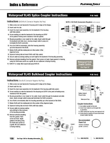
Waterproof RJ45 Splice Coupler Instructions P/N 740C
Instructions (EACH RJ45 Connector Requires this Prep) NOTE: 2 EA RJ45 Connectors Required (not included)
1) Slide screw nut over backend of housing until it stops at the flange.
2) Insert seal into clip.
3) Insert the clip & seal assembly into the backend of the housing
until fully seated.
4) Screw sealing nut onto the backend of the housing and STOP
at the point of feeling some resistance from the gasket. #3
5) Housing assembly is now ready for the cable. Insert cable through
the backend and slide down, leaving enough cable to prep and #1
terminate the RJ45 connector. #4
6) Once the RJ45 is terminated, slide the housing assembly Seal Nut
up to the backend of the RJ45. Clip Gasket
Seal
7) Rotate RJ45 until the locking tab is in the center of the
alignment pins. #2 Screw Nut
8) Squeeze locking tab and insert RJ45 until fully seated. Housing
9) Secure cable by turning sealing nut until tight at the backend of the housing assembly. #10
10) Remove adhesive backing from the gasket. Push screw nut back. Apply gasket to housing
using the RJ45 nose profile as a guide. Be sure adhesive is facing housing. Waterproof RJ45
11) RJ45 #1 is ready. Now repeat and prep RJ45 #2. Coupler System
See Page 52
Waterproof RJ45 Bulkhead Coupler Instructions P/N 741C
Instructions (The RJ45 Connector Requires this Prep)
1) Slide screw nut over backend of housing until it stops at the flange.
2) Insert seal into clip.
3) Insert the clip & seal assembly into the backend of the housing until fully seated.
4) Screw sealing nut onto the backend of the housing and STOP at the point of feeling some
resistance from the gasket. Rubber Gasket Plastic
Placed Inside Nut
5) Housing assembly is now ready for the cable. Insert cable through the backend and slide
down, leavin enough cable to prep and terminate the RJ45 connector.
Waterproof Cap
6) Once RJ45 is terminated, slide the housing assembly up to the backend of the RJ45.
7) Rotate RJ45 until the locking tab is in the center of the alignment pins. Coupler Instructions
8) Squeeze locking tab and insert RJ45 until fully seated. 1) lace rubber gasket on the end.
9) Secure cable by turning sealing 2) Insert from inside to out through hole
nut until tight at the backend in panel/box.
of the housing assembly. #2 3) Slide waterproof cap ring over exposed end.
4) Screw down on plastic nut and cinch down.
10) Remove adhesive backing DO NOT OVER TIGHTEN
from the gasket. Push
screw nut back. Apply #1
gasket to housing using Recommended
the RJ45 nose profile as Seal Nut Panel Cut
a guide. Be sure adhesive Clip Gasket 19.4mm x 20.8mm
is facing housing. Seal (0.760" x 0.815")
#6
Screw Nut
Housing
#10
108 See Page 106 For Warning Information Phone: 800.749.5783 Fax: 800.749.5784