
Page 5 - 英格索兰附件图册IngersollRand
P. 5
5
When selecting an FRL or individual filter, regulator, and lubricator units, the air consumption of the tools ( ) * + 5 , - 6
S=>= ?@A BCD
Sets . / 2
or equipment to be serviced should be correlated with the flow capacity of the FRL. ARO Filters, Regulators, ) 0 7 , -
and Lubricators are designed to flow in excess of that indicated in the maximum recommended flow table 1 8 2 3 * + 3 4
shown below. This table gives recommended flows for pipe sizes at listed pressures and should be used as + - 4 . -
a guide in sizing piping and equipment for compressed air systems. . /
Maximum recommended air low (scfm) thru ANSI standard weight Schedule 40 pipe
Applied Nominal Standard Pipe Size — Inches
Pressure
PSIG 1/8" 1/4" 3/8" 1/2" 3/4" 1" 1-1/4" 1-1/2" 2" 2-1/2" 3"
5 0.5 1.2 2.7 4.9 13 27 40 80 135 240
10 0.8 1.7 3.9 7.7 11.0 21 44 64 125 200 370
9:9
20 1.3 3.0 6.6 13.0 18.5 35 75 110 215 350 600
40 2.5 5.5 12.0 23.0 34.0 62 135 200 385 1100
60 3.5 8.0 18.0 34.0 50.0 93 195 290 560 900 1600
9;<
80 4.7 10.5 23.0 44.0 65.0 120 255 380 720 1200 2100
100 5.8 13.0 29.0 54.0 80.0 150 315 470 900 1450 2600
150 8.6 20.0 41.0 80.0 115 220 460 680 1350 2200 3900
200 11.5 26.0 58.0 108.0 155.0 290 620 910 1750 2800 5000
250 14.5 33.0 73.0 135.0 200 370 770 1150 2200 3500 6100
The flow values in the chart above are based upon a pressure drop ( ∆P) as set forth in the following schedule:
Pressure Drop (ΔP) per 100 ft. of Pipe Pipe Size — Inches VT V RVT U
RV
PPQO
N O L L
T
RST URST
R
;
J
L
H
K
I
M
I
<F G
T
RVT
N O L L
PPQO
T
UR; T
R
;
M
I
I
L
WF G
H
K
J
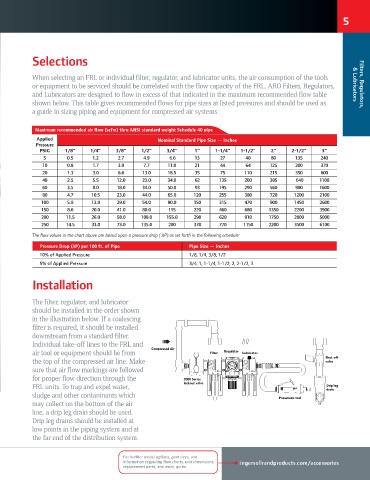
The filter, regulator, and lubricator
ICD @E>>E@ABC
should be installed in the order shown
in the illustration below. If a coalescing
filter is required, it should be installed
downstream from a standard filter.
Individual take-off lines to the FRL and
Compressed Air
air tool or equipment should be from Filter Regulator Lubricator
Shut-off
the top of the compressed air line. Make valve
sure that air flow markings are followed
for proper flow direction through the 2000 Series
lockout valve
FRL units. To trap and expel water, Drip leg
drain
sludge and other contaninants which Pneumatic tool
may collect on the bottom of the air
line, a drip leg drain should be used.
Drip leg drains should be installed at
low points in the piping system and at
the far end of the distribution system. # $% &
! "
#
"
"
"
&
" #
"
'
"